

 français
 English
 Deutsch
 español
 العربية
 中文
中文
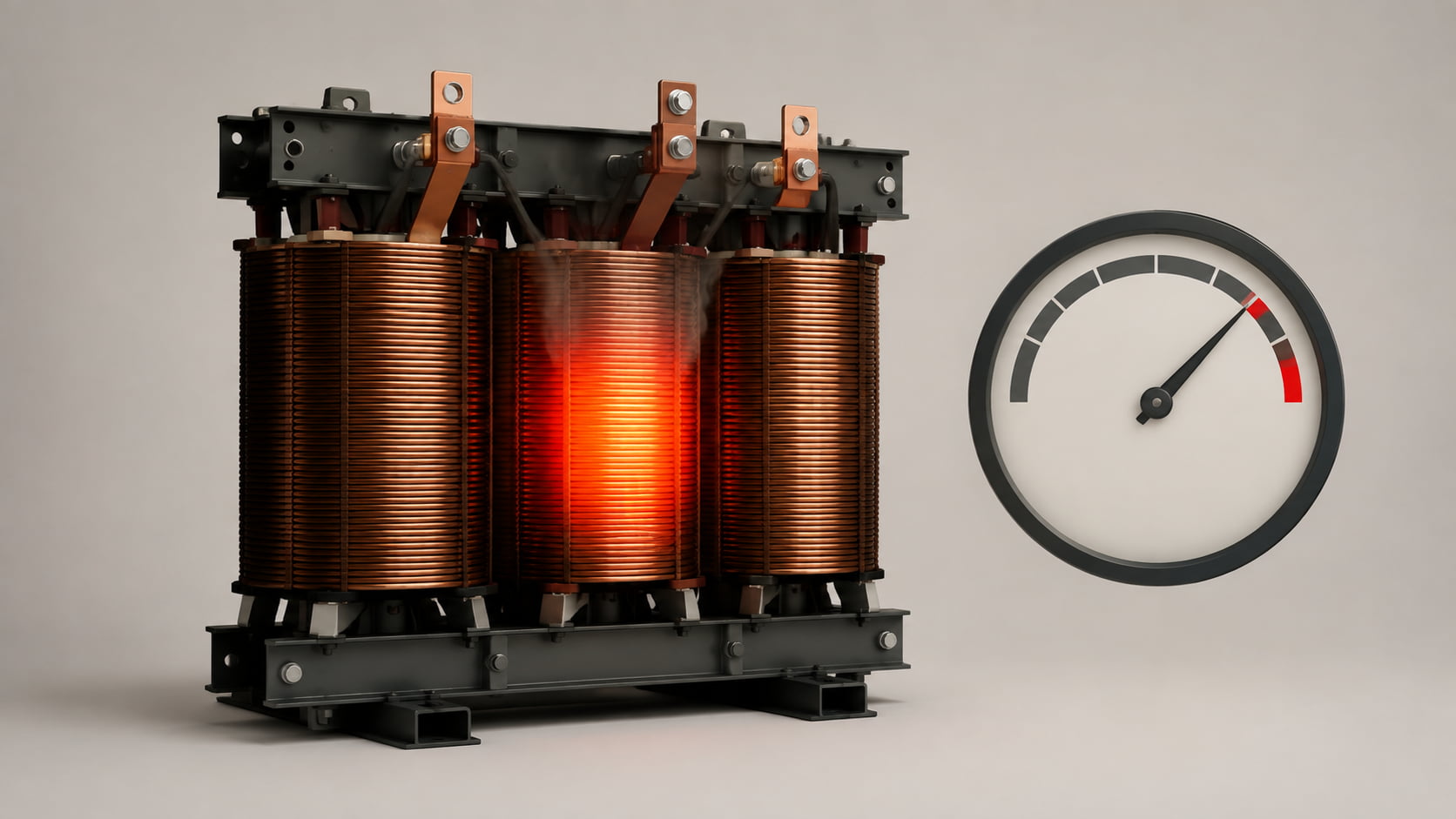
Un transformateur peut chauffer anormalement même lorsque la charge connectée semble largement inférieure à sa valeur nominale. Le courant peut paraître acceptable alors que la température des enroulements ou du boîtier continue d'augmenter.
Cela se produit souvent car la charge est évaluée uniquement en kilowatts ou en ampères moyens. Les harmoniques, les déséquilibres, un faible facteur de puissance et un refroidissement insuffisant peuvent générer une chaleur supplémentaire sans déclencher d'alarme de surcharge.
Trouver la cause nécessite plus que de vérifier le pourcentage de charge totale.
La surchauffe d'un transformateur se produit lorsque la production de chaleur interne dépasse la capacité de l'appareil à la dissiper.
Les pertes d'un transformateur comprennent les pertes dans le noyau et dans les enroulements. Les pertes dans les enroulements augmentent approximativement avec le carré du courant efficace :
Pertes de cuivre ≈ I²R
Une augmentation de courant de 10 % accroît les pertes par effet Joule d'environ 21 %. Les harmoniques ajoutent des pertes par courants de Foucault et par flux de fuite, de sorte que des courants RMS égaux ne produisent pas toujours un échauffement égal.
La puissance nominale en kVA est calculée pour une tension, une fréquence, un refroidissement, des conditions ambiantes et une forme d'onde du courant spécifiés. Des conditions différentes peuvent réduire la capacité utile.
| Conditions de fonctionnement | Ce que montre un contrôle de charge de base | Que se passe-t-il réellement ? |
|---|---|---|
| Courant harmonique élevé | Le courant RMS semble acceptable | Les pertes supplémentaires par courants de Foucault augmentent le chauffage. |
| Facteur de puissance faible | La puissance en kW reste inférieure à la puissance nominale du transformateur. | Un courant supplémentaire est nécessaire pour obtenir la même puissance utile. |
| Déséquilibre de phase | La charge triphasée moyenne semble normale | Un enroulement peut être fortement chargé |
| température ambiante élevée | La charge électrique est dans les limites | La marge de refroidissement est réduite. |
| Tension excessive ou basse fréquence | Le courant peut ne pas paraître excessif. | Les pertes liées au flux du noyau et à l'excitation augmentent |
Les variateurs de fréquence, les systèmes d'alimentation sans coupure, les redresseurs, les chargeurs de véhicules électriques et les alimentations électroniques consomment un courant non sinusoïdal qui augmente l'échauffement du transformateur.
Les courants harmoniques augmentent les pertes par effet Joule, tandis que les composantes de haute fréquence accroissent les pertes par courants de Foucault et les pertes parasites. Une charge de 600 A présentant des distorsions peut donc générer plus de chaleur qu'une charge de 600 A quasi sinusoïdale.
Le spectre est important, tout comme le taux de distorsion harmonique total (THD) du courant. Les installations présentant une charge non linéaire importante peuvent nécessiter une réduction de puissance harmonique ou un transformateur conçu pour les courants distordus.
Les harmoniques de troisième ordre et leurs multiples sont en phase et s'ajoutent au neutre d'un système triphasé à quatre fils au lieu de s'annuler.
Les ordinateurs, l'éclairage LED et les alimentations monophasées peuvent donc produire un courant neutre élevé, ce qui ajoute de la chaleur aux conducteurs, aux connexions et aux enroulements.
Une répartition inégale des charges monophasées peut également pousser un enroulement près de sa limite, même si la puissance apparente triphasée totale semble acceptable. Mesurez les courants de phase et de neutre individuellement ; c’est la phase la plus chaude, et non la moyenne, qui détermine la contrainte thermique.
La charge du transformateur dépend de la puissance apparente (kVA) et du courant, et pas seulement des kilowatts utiles (kW). Un faible facteur de puissance nécessite un courant plus élevé pour une même puissance active.
Une charge de 400 kW avec un facteur de puissance de 0,80 nécessite 500 kVA. À 0,95, elle nécessite environ 421 kVA. La première condition engendre un courant d'enroulement et des pertes par effet Joule (I²R) plus importants.
Les batteries de condensateurs corrigent le facteur de puissance par déplacement, tandis que la distorsion harmonique peut nécessiter un filtre actif. L'ajout de condensateurs sans vérification préalable des harmoniques peut engendrer une résonance.
Un transformateur correctement chargé peut surchauffer en raison d'une ventilation obstruée, de ventilateurs défectueux, de poussière, d'un dégagement insuffisant, de la lumière directe du soleil ou d'une température ambiante élevée.
Les transformateurs secs dépendent de la circulation de l'air. Un local électrique exigu ou une enceinte restrictive peuvent augmenter la température d'entrée et réduire la capacité disponible.
Pour les groupes motopropulseurs à bain d'huile, un niveau d'huile insuffisant, un radiateur obstrué ou une panne de pompe peuvent avoir le même effet. Il convient d'évaluer la température en tenant compte des conditions ambiantes et de refroidissement.
Une tension excessive ou une fréquence réduite augmentent le nombre de volts par hertz et peuvent pousser le noyau du transformateur vers la saturation.
Le courant de magnétisation, le bruit et l'échauffement du noyau peuvent alors augmenter même à charge secondaire modérée. Parmi les causes possibles, on peut citer des prises incorrectes ou une tension et une fréquence instables du générateur.
Mesurez la tension et la fréquence aux bornes ; un courant secondaire normal n’exclut pas une surexcitation.
| Symptôme | Cause probable | Que mesurer ou inspecter |
| La température augmente à mesure que la charge du variateur de fréquence augmente. | Courant harmonique et pertes supplémentaires | THDi, spectre et courant RMS |
| Le conducteur neutre est plus chaud que les conducteurs de phase. | Harmoniques triples ou déséquilibre de charge | Courant neutre et troisième harmonique |
| Un enroulement ou une borne est beaucoup plus chaud | Déséquilibre de phase ou connexion lâche | Courant par phase et image thermique |
| Le transformateur reste chaud même à charge modérée. | Mauvaise ventilation ou température ambiante élevée | Entrée d'air, débit d'air et fonctionnement du ventilateur |
| Bourdonnement fort accompagné d'une hausse de température | Surtension, basse fréquence ou harmoniques | Tension, fréquence et forme d'onde |
| Point d'accès local à une connexion | Joint lâche, corrodé ou endommagé | Image thermique et résistance de connexion |
Effectuez des mesures électriques et thermiques simultanées. Une seule mesure de courant ne permet pas de distinguer les problèmes de surcharge, de distorsion et de refroidissement.
Enregistrer:
RMS voltage and current on every phase
kW, kVAr, kVA and true power factor
Current and voltage THD
Individual harmonic orders
Neutral current
Transformer and room temperature
Loading over a complete operating cycle
Thermal images of terminals, windings and cooling surfaces
Compare temperature with load changes during light load, normal production, peak demand and switching of major nonlinear equipment.
| Confirmed condition | Possible solution |
| High harmonic current | Apply an AHF, drive reactor, DC choke or suitable passive filter |
| Transformer is unsuitable for nonlinear loads | Derate it or use a correctly selected K-rated transformer |
| High neutral current | Rebalance loads and mitigate triplen harmonics |
| Low displacement power factor | Apply correctly sized reactive power compensation |
| Rapid or unbalanced reactive demand | Use dynamic per-phase compensation |
| Poor ventilation | Restore airflow, fans, clearances and room cooling |
| Excessive V/Hz | Correct taps, voltage regulation or frequency control |
Size an Active Harmonic Filter from measured harmonic current, not transformer capacity. Position its current transformers to measure the responsible loads.
Yes. Harmonics create additional copper, eddy-current and stray losses, so a transformer below nameplate current can still exceed its thermal limit.
The limit depends on transformer type, insulation class, cooling method and ambient temperature. Compare readings with the manufacturer’s specified temperature rise.
It can reduce current when low displacement power factor is the cause. If distortion is responsible, capacitors may not solve the problem and could introduce resonance.
A K-rated transformer tolerates additional heating from specified nonlinear loads. It does not remove harmonics; it is designed to carry them safely.
Measure at the transformer secondary and major nonlinear feeders. Phase and neutral readings help identify whether one load group is responsible.
Transformer overheating below rated load indicates that harmonics, imbalance, poor power factor, cooling or volts per hertz may have been overlooked.
Diagnosis requires electrical logging, harmonic analysis and thermal inspection. Solutions may include load balancing, better ventilation, power factor correction, harmonic mitigation or transformer derating.
L'évaluation conjointe de la qualité du signal et de la température est plus fiable que la comparaison du courant moyen avec la valeur nominale.



 réseau ipv6 pris en charge