

 français
 English
 Deutsch
 español
 العربية
 中文
中文
SVG and AHF Components: What Determines Accurate and Long-Term Performance?
A 400 V plant may install two power-quality cabinets with the same rated current and expect the same result. Months later, one follows peak load while the other derates, produces more acoustic noise, or leaves compensation error at the point of common coupling (PCC). The difference lies in the sensing chain, power stage, magnetic components and thermal path.
SVG and AHF Performance depends on more than basic operation. Component quality and matching determine compensation accuracy, dynamic response, full-load capability, power loss, acoustic noise and long-term stability.
An Active Harmonic Filter (AHF) measures load current and injects opposite-phase harmonic current. A suitable three-phase four-wire design may also address neutral current and load unbalance. A Static Var Generator (SVG) measures voltage and current, then supplies or absorbs reactive current to support power factor and voltage stability.
Their control objectives differ, but both require accurate sensing, a fast IGBT converter, stable DC-link storage, correctly designed reactors and reliable cooling. A high-capacity IGBT stage cannot compensate accurately with a phase-error CT reference, and a tuned controller cannot sustain rated current after the DC-link or cooling path reaches its thermal limit.
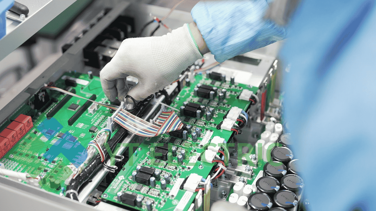
The CT and voltage-sensing circuit define what the controller sees. Their ratio, accuracy class, phase displacement, polarity, placement and wiring must match software configuration. A saturated, reversed or mismatched CT gives the controller a distorted reference and can cause under-compensation, over-compensation or an unstable current loop.
For AHF, sensing error leaves residual harmonic current or misdirects harmonic priority. For SVG, it shifts the reactive-current reference and reduces power-factor correction accuracy. High-precision sensing is the first condition for repeatable compensation.
The IGBT module converts the controller command into compensation current. Its current rating, voltage margin, switching behavior and thermal capability affect AHF harmonic tracking and SVG reactive-current response. The gate driver must apply consistent switching commands, maintain suitable dead time and respond correctly to protection events.
The DC-link capacitor stabilizes bus voltage and absorbs ripple-energy exchange. Ripple-current capability, equivalent series resistance, temperature rating and lifetime influence bus ripple, converter loss and sustained output. A capacitor selected only by nominal capacitance can age quickly under high ripple and elevated cabinet temperature.
IGBT switching and conduction loss, driver timing and capacitor ripple stress must be assessed together at the customer’s actual voltage, load profile and ambient condition.
|
Critical component |
Key quality and design checks |
Main performance affected |
Risk when poorly matched |
|
CT and voltage sensing |
Accuracy, phase error, ratio, saturation margin, polarity |
Compensation accuracy |
Residual harmonics, reactive-power error or unstable control |
|
IGBT module and gate driver |
Current margin, switching consistency, protection response |
Dynamic response and loss |
Slow tracking, overheating or nuisance trips |
|
DC-link capacitor |
Ripple-current rating, ESR, temperature life |
DC-bus stability and full-load endurance |
Excess ripple, derating and reduced lifetime |
|
Coupling reactor |
Inductance tolerance, saturation margin, winding construction |
Ripple, noise and current control |
Higher distortion, audible noise and thermal stress |
|
Cooling and busbar system |
Airflow, fan life, contact resistance, temperature monitoring |
Continuous operation and stability |
Hot spots, output derating and accelerated ageing |
The coupling reactor controls current ripple and converter tracking. Core selection, winding design, saturation margin, insulation and mechanical fixation influence copper loss, core loss, audible vibration and reliability.
Noise can come from reactor magnetostriction, winding vibration, fan speed, airflow resistance and cabinet panels. Low-noise operation requires coordinated reactor selection, rigid mounting, air-path design and fan control.
Busbars, terminals, protective devices and cable routing also matter. High contact resistance creates local heating, while uneven current paths add loss and reduce thermal margin.
A three-level converter adds an intermediate voltage level. With suitable modulation and layout, it can produce smaller AC voltage steps than a two-level arrangement, helping reduce effective dv/dt and current ripple. Its benefit still depends on modulation, component selection, neutral-point control and magnetic design.
At 45°C ambient, IGBT junction temperature, capacitor temperature, reactor rise, heat-sink capacity, airflow, fan performance and dust accumulation determine continuous full-load operation. A short functional test cannot prove thermal margin.
YT Electric should document ambient condition, ventilation clearance, temperature monitoring and derating boundary during technical clarification.
The right configuration begins with site data: voltage, wiring, load profile, harmonic spectrum, reactive-power demand, PCC target, generator or UPS interaction, ambient temperature, dust level and installation clearance. The result may require an AHF, an SVG, a hybrid strategy or coordination with an existing capacitor bank.
|
Operating condition |
Main design risk |
Required review |
YT Electric customization focus |
|
VFD-dense manufacturing line |
Changing harmonic spectrum and current peaks |
CT position, harmonic priority, reactor current margin |
AHF rating, 3P3W/3P4W arrangement and control settings |
|
Low power factor with rapid load changes |
Reactive-current demand and voltage movement |
Voltage sensing, IGBT current margin, control response |
SVG capacity and reactive-power control strategy |
|
45°C electrical room |
Thermal derating and capacitor ageing |
Airflow, fan duty, heat-sink margin and alarms |
Cabinet ventilation, component margin and temperature monitoring |
|
Dusty industrial location |
Air-path blockage and hot spots |
Filter maintenance, clearance and service access |
Enclosure layout and maintenance plan |
|
Generator or UPS-supported bus |
Protection coordination and dynamic interaction |
Current limit, transfer sequence and staged tests |
Control coordination and commissioning plan |
Consider a representative 400 V, three-phase, four-wire site with VFD-driven equipment and a warm electrical room. Cabinet noise rises and output derates during the high-load shift although installed capacity appears sufficient.
The investigation compares PCC current, CT signals, DC-bus behavior, IGBT and capacitor temperatures, reactor vibration, fan operation and airflow. The solution may revise CT arrangement, reactor saturation margin, DC-link ripple capability or cabinet thermal design.
Verify compensation error, response during load changes, temperature rise, noise observation and continuous-current stability. Without authorized data, do not claim a specific reduction percentage, efficiency figure or customer name.
No. Rated current does not confirm sensing accuracy, DC-link ripple capability, reactor saturation margin or thermal endurance. Review the complete design boundary.
CTs, IGBT modules and drivers, DC-link capacitors, coupling reactors, fans, busbars and protection devices all require electrical, thermal and mechanical matching.
Only when the supplier defines the ambient condition, thermal margin, ventilation path, component temperatures and derating boundary for that installation.
Provide a single-line diagram, voltage and wiring details, power-quality record, load schedule, installation environment and required acceptance target.
SVG and AHF systems should be evaluated as coordinated power-electronic assemblies, not as cabinets defined only by rated current. CTs determine the reference, IGBTs and drivers determine current response, DC-link capacitors stabilize energy exchange, reactors control ripple and noise, and thermal construction protects continuous operation.
YT Electric supports customizable needs based on single-line diagram, power-quality record, load schedule and site environment to configure a solution that aligns component selection with the required compensation accuracy, response speed, full-load endurance and long-term stability.
Explore YT Electric product specifications and application guidance: https://www.ytelect.com/blog/guide-to-selecting-active-harmonic-filters_b321
Reference: IEEE 519-2022, IEEE Standard for Harmonic Control in Electric Power Systems: https://standards.ieee.org/ieee/519/10677/
Need a site-specific solution? Share your single-line diagram, load list, measured power factor, THDi/TDD data, and ambient conditions with YT Electric. Our sales engineers can review the data and prepare a technical proposal



 réseau ipv6 pris en charge