

 français
 English
 Deutsch
 español
 العربية
 中文
中文
SVG Reactive Power Compensation:
Beyond PF Correction
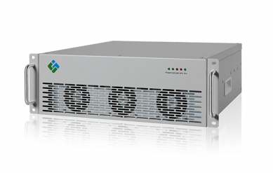
A capacitor bank supplies fixed or switched capacitive kvar. It works when the load is relatively stable, the network is not harmonic-rich, and switching delays do not matter. It becomes a weak fit when VFDs, rectifiers, welding loads, or UPS front ends make reactive demand change faster than contactors or thyristor steps can follow.
An SVG measures the load-current vector and injects controlled reactive current through a voltage-source converter. It commands leading or lagging current in each cycle range, holding a power-factor target as the load changes and supporting bus voltage during an inductive load increase.
A low PF may result from continuous inductive demand, a lightly loaded transformer, or restricted generator reactive reserve. A 480 V data-center bus can also combine UPS input stages, cooling drives, non-linear IT loads, and capacitor steps—an arrangement that requires harmonic assessment before selecting an SVG.
Mining crushers, steel rolling equipment, arc-related loads, and textile drives create rapid reactive-current steps. Feeder and transformer impedance convert those steps into voltage drop; SVG reduces the reactive component at LV, while STATCOM applies the same function where MV duty requires it.
|
Technology |
Reactive-current response |
Harmonic interaction |
Voltage-support use |
Engineering limitation |
|
Switched capacitor bank |
Discrete steps; limited by switching method |
Can resonate with network inductance and harmonic spectra |
Limited between steps |
Best for steady, low-harmonic loads |
|
LV SVG |
Continuous controlled kvar output |
Does not replace an AHF for broad harmonic-current cancellation |
Supports LV bus voltage during load steps |
Capacity and short-circuit coordination must match the LV system |
|
Active Harmonic Filter (AHF) |
Can supply configured reactive current while cancelling selected harmonics |
Direct harmonic mitigation and neutral-current compensation, depending on configuration |
Indirect benefit by reducing distortion-related loading |
Current rating is shared among harmonic, reactive, and imbalance duties |
|
MV STATCOM |
Continuous dynamic reactive output at medium voltage |
Usually paired with a harmonic study or filtering strategy |
Stronger feeder and bus-voltage stabilization |
Requires MV protection, layout, and grid-study coordination |
Table A. Selection differences: the converter function must match the dominant disturbance, not just the monthly PF value.
Harmonic current does not vanish because an SVG corrects displacement power factor. A six-pulse drive, UPS rectifier, or uncontrolled rectifier draws non-sinusoidal current; that current produces additional I²R loss in cable, switchgear, and transformer windings. It also raises eddy-current and stray losses in magnetic components, so transformer heating can rise even when the fundamental current appears acceptable.
Zero-sequence triplen harmonics require a separate check in four-wire systems. Third, ninth, and fifteenth harmonic currents on each phase are in phase with one another in the neutral conductor instead of cancelling, so the neutral can carry a current above the phase fundamental expectation. That condition can overheat neutral conductors, terminals, and distribution-board connections; an AHF configured for neutral current compensation is usually the relevant technology, not an SVG alone.
High THDi changes capacitor-bank risk because capacitor impedance falls as frequency rises and can resonate with network inductance. Measure the spectrum before retaining capacitors; specify detuned reactors only after checking tuning and thermal duty.
A 3-level topology synthesizes voltage in smaller steps than a 2-level bridge, reducing output dv/dt and potentially lowering insulation, common-mode, and filter stress. SPWM turns the current reference into gate signals, so clean sensing, correct CT polarity, and stable loop tuning are essential to compensation accuracy.
Si IGBT modules suit many industrial duties, while SiC MOSFETs can reduce switching loss at higher frequency; actual loss still depends on voltage, current, modulation, and thermal resistance. At 45°C ambient, specify full-load kvar at real cabinet inlet temperature, with allowance for fan condition, filter clogging, and altitude derating.
|
Site condition |
Measurements that govern selection |
Recommended configuration |
Capacity logic |
Installation and maintenance focus |
|
PF persistently below target; low THDi |
15-minute kvar trend, transformer loading, PF target |
LV SVG or stepped capacitors after harmonic check |
Select from peak inductive kvar plus operating margin; avoid sizing from kVA alone |
Check feeder protection and CT placement |
|
480 V UPS and VFD bus with elevated THDi |
Harmonic spectrum, neutral current, AHF current reserve, UPS impedance |
AHF with reactive-current function; SVG only if kvar demand is separately dominant |
Reserve AHF current for harmonics first, then reactive and imbalance demand |
Coordinate with UPS bypass paths and maintenance windows |
|
Rapid motor, crusher, rolling, or welding load |
Step magnitude, ramp time, bus-voltage trend, short-circuit level |
LV SVG for LV bus; evaluate STATCOM at MV PCC |
Size from largest repeatable reactive step and required recovery behavior |
Verify protection coordination, ventilation, dust ingress control |
|
Hot, dusty industrial room |
Cabinet inlet temperature, altitude, contamination, clearance |
Derated SVG/AHF cabinet or conditioned electrical room |
Use manufacturer thermal curves at actual inlet temperature |
Clean filters, inspect fans and terminals on a scheduled basis |
|
Existing capacitor-bank trips or fails |
Harmonic orders, resonance scan, capacitor temperature, breaker events |
Harmonic study; AHF and/or SVG after capacitor strategy is redesigned |
Do not add kvar until resonance and switching duty are resolved |
Isolate or detune legacy stages only under an approved design |
Table B. Engineering selection requires electrical measurements, environmental duty, and protection coordination.
Consider a representative 480 V North American data-center expansion, not a named customer project. UPS input stages, server power supplies, EC fans, and VFD chillers share a low-voltage bus; low-load periods and cooling transitions produce poor PF, high neutral current, and capacitor-stage alarms.
UPS and IT loads add non-linear current, while VFD demand changes the reactive profile. An SVG alone would improve kvar response but would not cancel the dominant harmonic and zero-sequence current.
The engineering sequence monitors the service and critical distribution sections, checks capacitor resonance, then sizes an AHF first for measured harmonic and neutral current. It reserves remaining AHF current for reactive compensation and adds SVG only if peak kvar demand exceeds that headroom; UPS compatibility, protection, and bypass conditions are verified before energization.
Acceptance criteria are stable PF within the agreed operating band, current THDi at the monitored PCC within the applicable limit, neutral current within equipment ratings, and removal or redesign of problematic capacitor stages. These are design targets, not claimed project results; actual performance depends on spectrum, source impedance, load diversity, and settings.
Log kvar demand, identify the largest sustained reactive step, and add a justified margin. Confirm available kvar at actual ambient temperature and altitude; do not treat SVG rating as AHF harmonic-current capacity.
The method depends on isolation design, feeder availability, CT and breaker work, and local safety procedure. Most sites schedule a planned outage for final termination and protection testing after reviewing the single-line diagram.
Inspect filters, fans, terminations, controller alarms, and cabinet environment on a schedule suited to dust, temperature, and operating hours. Capacitor systems also require checks for capacitance change, reactor condition, and thermal stress.
Yes, after an engineering review of generator reactive reserve, UPS control, system impedance, capacitor resonance risk, and CT location. A monitored commissioning plan identifies control interaction before it becomes a fault diagnosis issue.
SVG Reactive Power Compensation gives a facility fast kvar control, but it should be specified as part of a measured power-quality strategy. Use SVG for dynamic reactive demand and voltage support, use an AHF where harmonic and neutral-current cancellation govern the outcome, and evaluate STATCOM when medium-voltage load steps affect feeder stability.
YT Electric can review load profiles, harmonic measurements, thermal conditions, and single-line diagrams to define the correct compensation architecture. The objective is measurable: place the right current-control function at the right bus, with capacity available under the site’s electrical and environmental duty.
Explore YT Electric product specifications and application guidance: https://www.ytelect.com/blog/guide-to-selecting-active-harmonic-filters_b321
Reference: IEEE 519-2022, IEEE Standard for Harmonic Control in Electric Power Systems: https://standards.ieee.org/ieee/519/10677/
Need a site-specific solution? Share your single-line diagram, load list, measured power factor, THDi/TDD data, and ambient conditions with YT Electric. Our sales engineers can review the data and prepare a technical proposal



 réseau ipv6 pris en charge