

 français
 English
 Deutsch
 español
 العربية
 中文
中文
Un générateur statique de puissance réactive est normalement évalué selon sa capacité en puissance réactive, son temps de réponse, son contrôle du facteur de puissance et sa compensation des harmoniques. Dans de nombreuses installations, la salle des équipements ajoute une autre exigence : la solution doit également contrôler le bruit, l'exposition à la poussière et les contraintes de maintenance.
Le générateur statique de puissance réactive sans ventilateur de YT Electric utilise la dissipation naturelle de la chaleur au lieu d'un ventilateur de refroidissement interne. La plate-forme SVG compacte assure une compensation de puissance réactive inductive et capacitive, ainsi qu'une compensation des harmoniques du rang 2 au rang 25.
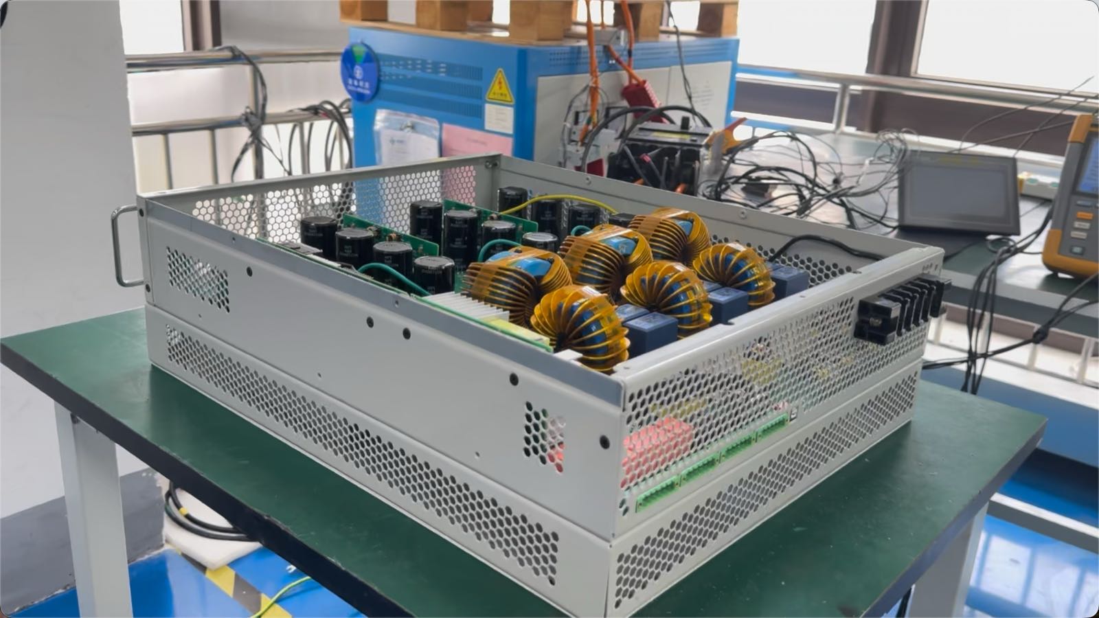
La différence la plus visible par rapport à une conception classique refroidie par ventilateur réside dans la méthode de refroidissement. La vidéo présente trois effets pratiques de la dissipation naturelle de la chaleur : un fonctionnement silencieux, une accumulation réduite de poussière autour des composants électroniques sensibles et moins de soucis de maintenance liés aux ventilateurs.
La fiche technique indique un niveau sonore ≤40 dB, une protection IP20, des dimensions de 440 × 578,5 × 175 mm et un poids répertorié de 28 kg. Ces valeurs aident à la planification des armoires, mais les installateurs doivent tout de même prévoir le dégagement requis, l'accès aux câbles et l'espace thermique nécessaire.
Une installation peut alterner entre des conditions arrière et avant au fur et à mesure que les moteurs, transformateurs, systèmes ASI, batteries de condensateurs et charges d'électronique de puissance changent d'état. Le SVG sans ventilateur prend en charge la compensation de puissance réactive inductive et capacitive dans la limite de la puissance nominale sélectionnée.
Les données fournies spécifient un PF≥0,99 comme référence de compensation réactive. Le résultat obtenu sur site dépend toujours de la disposition des TC, du point de mesure, du profil de charge, de la tension du réseau, de la capacité disponible et des réglages de mise en service. Le contrôle DSP+FPGA, une IHM LCD de 4,3 pouces ou 7 pouces et la communication Modbus sur RS485 facilitent la surveillance locale et l'intégration système.
La compensation de puissance réactive et le filtrage des harmoniques sont des tâches d'ingénierie distinctes. Une batterie de condensateurs peut corriger une partie d'un problème de facteur de puissance, mais elle n'élimine pas activement le courant harmonique. Lorsqu'un site présente un niveau d'harmoniques plus élevé, un filtre actif de puissance APF dédié annule le courant harmonique en temps réel. Pour les redresseurs, les variateurs de vitesse, les systèmes ASI et autres charges non linéaires, mesurez le spectre harmonique avant de choisir l'équipement.
La fiche technique spécifie une compensation du rang 2 au rang 25, une compensation sélective ou globale, et une capacité maximale de compensation des harmoniques égale à 100 % de la capacité nominale. Elle indique un taux de filtrage des harmoniques ≥95 %. Le résultat obtenu dépend du spectre harmonique, de l'impédance de la source, de la précision des TC, de la tension du réseau et de la capacité assignée à la charge harmonique.
Dans la vidéo, un analyseur de qualité de l'énergie Fluke et l'interface du produit montrent la compensation de puissance réactive en temps réel, l'amélioration du facteur de puissance vers 0,99 et le filtrage des harmoniques du rang 2 au rang 25. La démonstration indique un taux de filtrage allant jusqu'à 95 % avec un temps de réponse inférieur à 5 millisecondes.
Un dispositif de compensation doit réagir suffisamment vite pour suivre la charge. La fiche technique spécifie un temps de réponse total ≤5 ms et un temps de réponse instantané ≤50 μs ; il s'agit de points différents dans le processus de contrôle et de compensation.
Les équipes d'approvisionnement doivent demander comment le temps de réponse est mesuré, à quel point de fonctionnement, avec quelle forme d'onde de charge, et si la capacité sélectionnée peut fournir le courant requis. Mesurez le fonctionnement normal, la charge de pointe, les événements de commutation et les conditions à l'origine du problème de qualité de l'énergie.
| Considération d'ingénierie | SVG classique refroidi par ventilateur | Conception du SVG sans ventilateur YT Electric |
|---|---|---|
| Méthode de refroidissement | Flux d'air forcé par des ventilateurs internes | Dissipation naturelle de la chaleur |
| Conception acoustique | Le bruit du ventilateur dépend de la vitesse, du débit d'air et de la contamination | Niveau sonore de la fiche technique ≤40 dB |
| Exposition à la poussière | Le flux d'air peut aspirer la poussière à travers l'enveloppe et les filtres nécessitent une attention particulière | Aucun ventilateur de refroidissement interne ; l'environnement d'installation nécessite toujours une évaluation |
| Maintenance liée aux ventilateurs | L'inspection des ventilateurs et des filtres peut être nécessaire | Élimine le ventilateur interne en tant qu'élément de maintenance |
| Compensation réactive | Dépend du contrôle et de la puissance nominale du SVG sélectionné | Compensation inductive et capacitive |
| Compensation harmonique | Dépend du modèle et de la configuration | Compensation du 2e au 25e ordre ; compensation sélective ou complète |
| Communication | Dépend du modèle | Protocole Modbus via RS485 listé dans la fiche technique |
| Exigence d'installation | Dégagement pour ventilation forcée et accès au filtre | Dégagement pour dissipation thermique naturelle et vérification de la température ambiante |
Ce tableau compare les considérations de conception ; les ingénieurs doivent comparer les fiches techniques complètes, les conditions de service et les exigences de mise en service des modèles sélectionnés.
| Élément de sélection | Informations produit fournies | Ce que l'équipe de projet doit confirmer |
|---|---|---|
| Capacité nominale | 10 kvar ou 15 kvar | Courant réactif mesuré, FP cible et croissance future de la charge |
| Tension nominale | CA 400 V ±15% | Tension réelle du système et variation de tension au point de connexion |
| Fréquence | 50/60 Hz | Fréquence du réseau local et stabilité de fonctionnement |
| Connexion | Triphasé trois fils ou triphasé quatre fils | Disposition du conducteur neutre et point d'installation du TC |
| Plage harmonique | 2e au 25e ordre | Ordres harmoniques dominants et si une compensation sélective ou complète est requise |
| Réponse | Total ≤5 ms ; instantanée ≤50 μs | Performance dynamique requise et méthode de mesure |
| Refroidissement et bruit | Dissipation thermique naturelle ; ≤40 dB | Dégagement du panneau, température ambiante et exigence acoustique |
| Environnement | -20–30°C ; 0–95% HR, sans condensation ; altitude ≤1500 m | Déclassement, conditions de l'enceinte et ventilation du site |
| Communication | Modbus via RS485 | Plan de protocole BMS/EMS, tracé des câbles et planification des adresses |
La fiche technique indique que des températures ambiantes plus élevées réduisent la capacité de sortie. Au-dessus de 1500 m, la capacité est réduite de 1 % pour chaque tranche supplémentaire de 100 m. Ces limites doivent être vérifiées avant la finalisation de la commande, en particulier pour les boîtiers compacts ou les installations en haute altitude.
Commencez par une mesure de la qualité de l'énergie plutôt que par une estimation de la taille du transformateur. Enregistrez la tension, le courant, la puissance active, la puissance réactive, le facteur de puissance et les ordres harmoniques individuels au point de connexion prévu, en incluant les bancs de condensateurs, les équipements UPS et les filtres dans leurs états de fonctionnement.
Confirmez le type de connexion et la disposition des TC : les systèmes triphasés à trois fils et à quatre fils nécessitent des configurations de mesure et de compensation différentes. Vérifiez la polarité des TC, la séquence de phase et l'emplacement. Enfin, confirmez le dégagement pour le refroidissement naturel, l'accès à l'IHM, les conditions de service et les exigences RS485 avant la fabrication du panneau.
Aucune topologie de compensation unique ne convient à toutes les installations. Le SVG sans ventilateur est un candidat sérieux lorsque la capacité de 10 ou 15 kvar, le faible bruit acoustique et la dissipation thermique naturelle correspondent aux besoins mesurés. Les systèmes plus grands ou plus complexes peuvent nécessiter une plage de capacité différente ou un système de qualité de l'énergie coordonné.
Oui. Les informations fournies sur le produit répertorient la compensation de puissance réactive inductive et capacitive. La plage de fonctionnement finale dépend du modèle sélectionné, des paramètres de contrôle et de l'état mesuré du système.
La fiche technique répertorie la compensation harmonique du 2e au 25e ordre, avec une compensation sélective ou complète. Les ingénieurs doivent toujours mesurer le spectre harmonique du site et sélectionner le mode de compensation en fonction des ordres harmoniques dominants et de la capacité nominale disponible.
Confirmez la demande en kvar mesurée, le facteur de puissance cible, le courant harmonique, la tension, le type de câblage, la position des TC, la température ambiante, l'altitude et les exigences de communication. La valeur nominale de 10 kvar ou 15 kvar doit être sélectionnée en fonction des conditions de fonctionnement mesurées plutôt que de la seule puissance kVA du transformateur.
Le générateur statique de var (SVG) sans ventilateur allie compensation électrique et confort d'installation. La dissipation thermique naturelle élimine le ventilateur de refroidissement interne, tandis que le niveau sonore spécifié de ≤40 dB prend en charge les applications où le confort acoustique est important.
La plateforme YTPQC-SVG/xx-4-4L fournit une compensation de puissance réactive inductive et capacitive, une compensation harmonique du 2e au 25e ordre, une performance de référence PF≥0,99, un taux de filtre harmonique répertorié de ≥95 %, un temps de réponse total de ≤5 ms et une perte système de ≤2,5 %. La vidéo démontre ces fonctions avec un analyseur de qualité de l'énergie et l'interface du produit.
Lecture associée : les ingénieurs travaillant avec des usines utilisant beaucoup de VFD peuvent comparer les topologies de convertisseurs dans Filtre harmonique actif à 3 niveaux pour la correction du THDi.
Pour une recommandation spécifique au projet, partagez la tension, le profil kvar, le spectre harmonique, le type de connexion et les conditions d'installation avec YT Electric. Notre équipe spécialisée dans la qualité de l'énergie peut examiner l'adéquation et définir la configuration appropriée.
Contactez YT Electric pour une étude d'application SVG sans ventilateur et un devis de projet.



 réseau ipv6 pris en charge